Show and Tell
Let’s compare some different implementations of common filter types. As well as creating some audio examples, we’ll also explore different visual analysis tools to try and get a better handle of what’s going on.
We’ll start with the 12 dB/octave low-pass filter on an Oberheim OB-8. Incidentally, you may sometimes see this described as a ‘2-pole’ low-pass filter (where each ‘pole’ contributes 6 dB/octave of attenuation) but for our purposes they are the same thing.
The OB has a number of oscillator wave shapes. For this test we’ll stick to a sawtooth wave from one oscillator only, plus the built-in noise source.
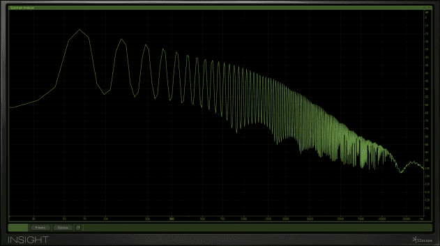
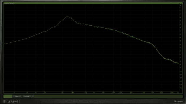
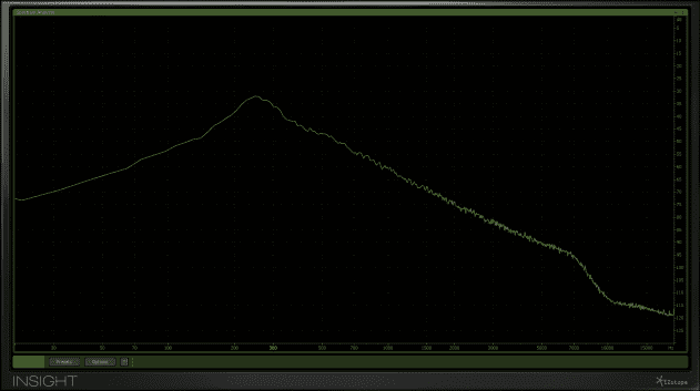
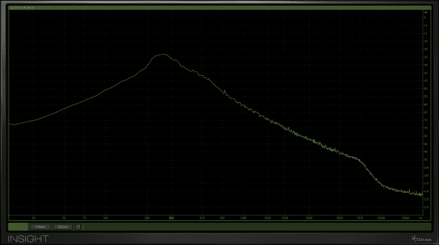
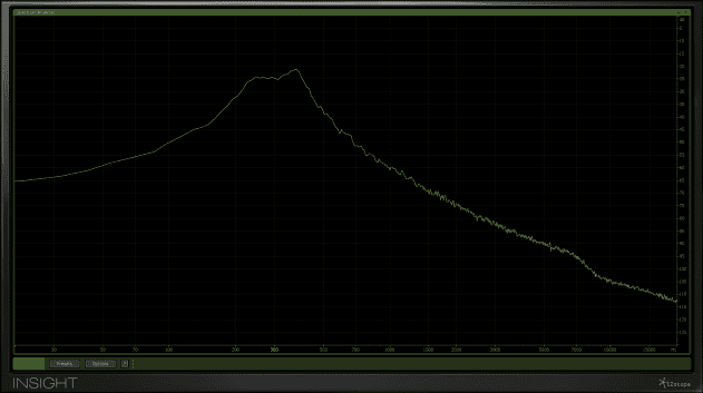
We can look at these as a frequency plot:
Note how the frequency content of the saw is made up of a fundamental frequency with harmonics of diminishing level. These harmonics occur as odd and even multiples of the fundamental. It’s also clear that both the saw and noise appear to be undergoing some tonal shaping even with the filter (apparently) fully open.
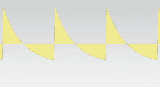
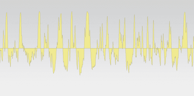
The wave shape is clearly visible in a DAW’s edit window:
Both appear appear to be somewhat asymmetrical, and the saw is certainly not a perfect angular sawtooth wave.
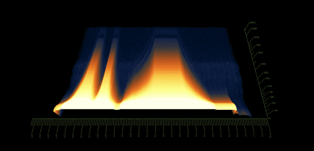
We can sweep the cutoff by hand, to get a better handle on the effect of the filter:
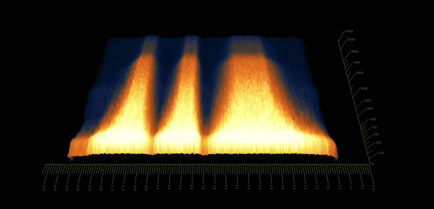
And to see this more clearly, a spectrogram analysis helps.
We can do a similar thing with the noise source.
The tests above miss out one critical aspect of most filters used in synths: resonance. Resonance (occasionally known as ’emphasis’ in Moog parlance or ‘peak’ in Korg’s terms) is used to shape the response of the filter, and also makes movement of the filter more pronounced. Filter resonance is achieved by the use of an internal feedback loop that increases the level of signals around the cutoff point. We can experiment with this on the OB.
This becomes very noticeable when the cutoff is controlled by an envelope.
The same also applies to plugins. This time we’re using a recording of the OB waves and processing them with Soundtoys’ FilterFreak:
The problem here is that whilst cutoff frequency can be set quite accurately, the audible result of moving from minimum to maximum resonance varies massively from one synth to the next. Even synths with the same filter IC can be designed be quite different in sonic terms – with some sounding relatively tame, whilst others whistle into full-on self-oscillation (where the filter generates a tone) and feedback at maximum resonance.
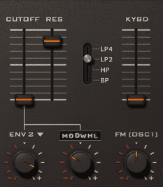
U-he’s Diva is considered to have one of the better implementations of digital filters that attempt to emulate their analogue counterparts. Their character is often most noticeable at higher resonance settings, when saturation and other artefacts come into play.


04.09 PM
Thanks !
Good basic article, but I would assume the typical reader of attack mag already pretty much knew about filter frequency charts resonance, poles, comb filters, etc.
It would have been maybe interesting after a short introduction covering these topics, to move on to discuss in more detail the phase effects of filters, the different uses and possibilities of modulations routes, what makes a moog, DSI, arturia filters, sound so different, etc…
03.35 AM
Good article! I enjoyed the example filter types (Oberheim, Korg, Moog, Arturia). I often look for ways to describe differences in filters. I also appreciated the learning that analogue filter slopes are rarely linear. Guess I’ll have to go play with Ableton Lives new Cytomic filter types.